Metered bulk supply
Maintain a stable product level without flooding the separator.
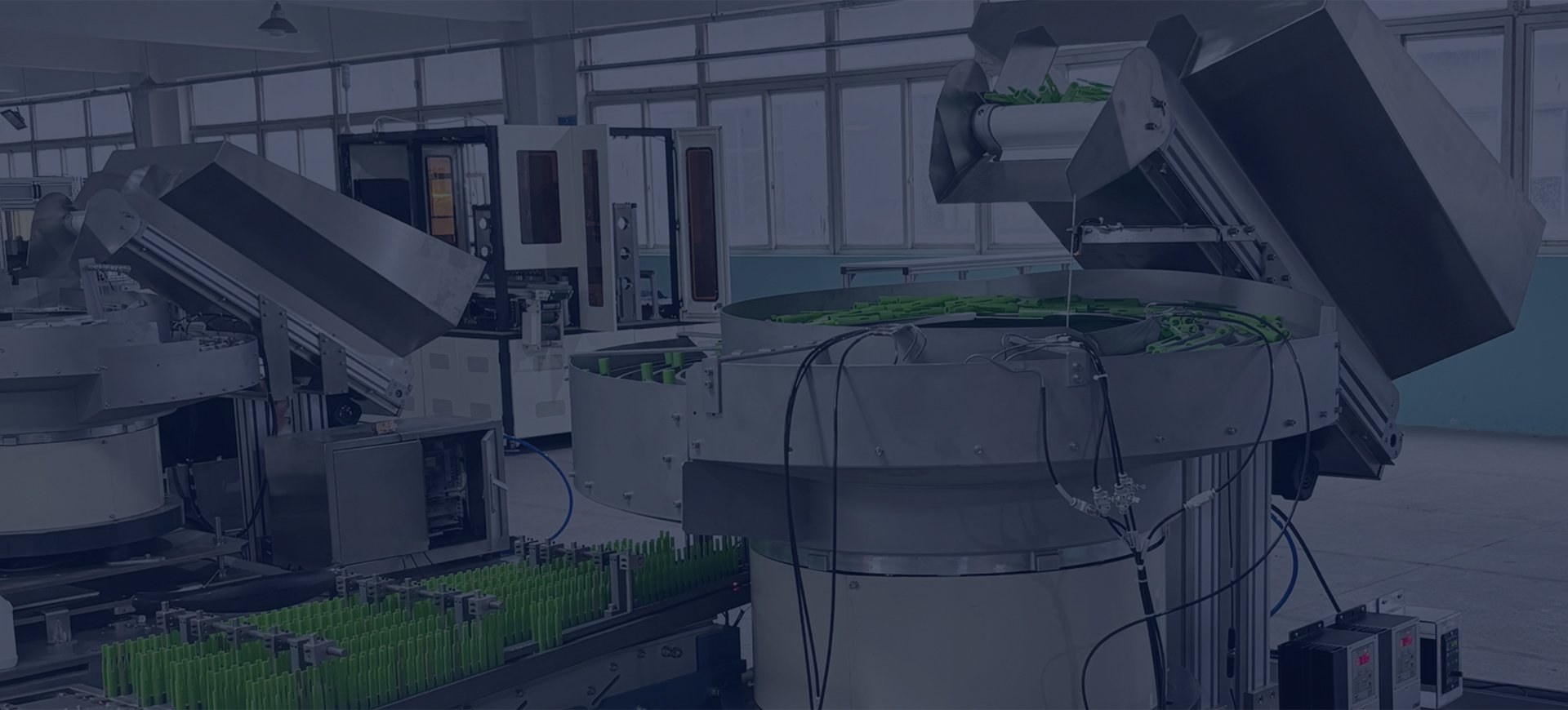
Automatic component counting systems
Application-engineered parts counting machines that separate loose components, verify each count and release the exact batch into a bag, box, kit or automated process.
The production problem
Counting loose components sounds simple until parts overlap, nest, bounce, arrive in doubles or continue moving after the target is reached. A robust system controls the complete flow—not only the sensor.
We develop the feed method, detection point, buffer, gate and container interface as one sequence, then prove it with representative production parts.
Counted output, ready for your process
From a single fastener format to multi-component kit preparation, the counter is designed around the accepted batch and hand-off condition.
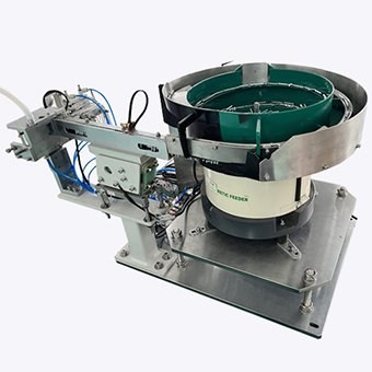
Preset quantities discharged to open bags, automatic baggers or sealing equipment.
Explore bag counting →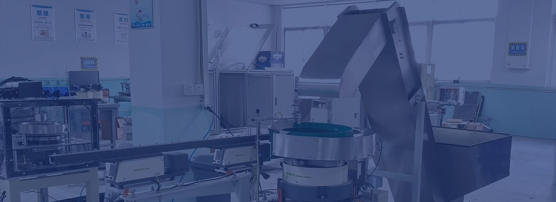
Controlled batches into cartons, totes, trays or conveyor-indexed containers.
Explore box counting →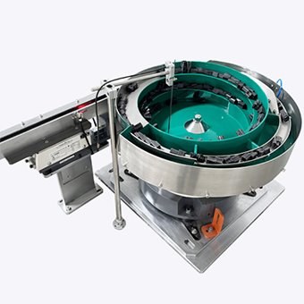
Coordinate several component feeders and verify each required quantity.
Explore kitting systems →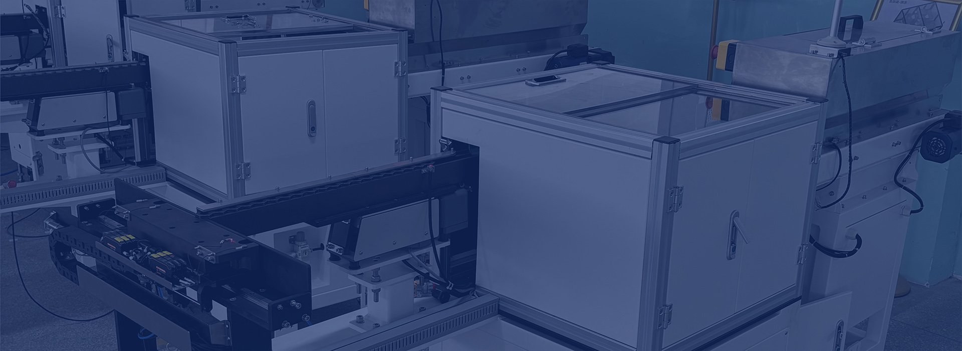
Release one part or a defined batch in response to a machine or operator request.
Explore process dispensing →Reliable count architecture
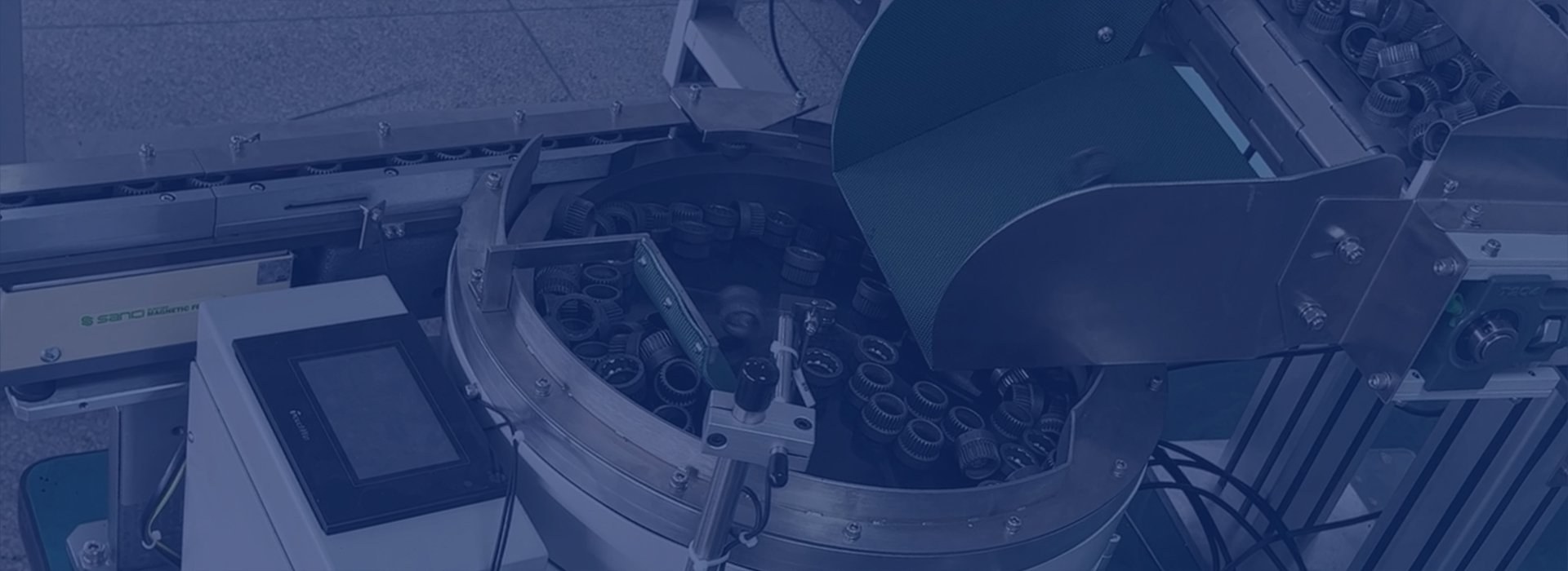
Accuracy depends on presenting one detectable part at a time, creating a clean batch boundary and managing every interruption without losing the count state.
See how component counters work →Maintain a stable product level without flooding the separator.
Prevent doubles, overlaps and side-by-side components at the detector.
Optical, fibre, laser, vision or alternative sensing matched to size and material.
Gate timing and buffering stop parts crossing between completed quantities.
Technology-neutral selection
Vibratory bowls suit many stable repeat components. Step feeders can offer gentle low-level loading. Linear tracks create buffer. Vision can count or verify difficult presentations. Counting by weight may be useful where individual separation is impractical and part mass is consistent.
Find the right counting route
Choose the closest application for direct technical answers, then send your component range for a sample-led recommendation.
Automatic counting for screws, nuts, bolts, washers, rivets and hardware kits.
Explore fastener counters →Count clips, O-rings, springs, mouldings, connectors and miniature components.
Explore small-parts systems →Compare photoelectric, fibre-optic, laser and light-curtain detection routes.
Explore optical counting →Understand when piece-weight sampling and automatic discharge are credible.
Explore weigh counting →Integrate preset component batches with open bags or automatic packaging machines.
Explore counting and packing →Compare methods, specification inputs, trials and factory acceptance evidence.
Choose a counting machine →See how vibratory bowls, linear buffers, optical sensors and batch gates work together.
Explore bowl feeder counting →Use controlled imaging for complex silhouettes, multiple objects and batch verification.
Explore camera counting →Find dedicated guidance for O-rings, plastic mouldings and loose electrical components.
Explore component applications →Component families
A sample-led project route
Component range, target quantity, rate, destination and acceptance.
Observe singulation, detection and stop accuracy using representative parts.
Resolve gates, containers, I/O, guarding, recipes and operator access.
Run defined challenge tests, recovery scenarios and production batches.
Frequently asked questions
Final suitability and performance remain subject to the actual component, operating conditions and agreed acceptance criteria.
Ask about your component →A component counting machine separates loose parts into a controlled stream, detects each passing item, accumulates a target quantity and releases the finished batch into a bag, box, kit, tray or production process.
Often yes, but suitability depends on geometry, size range, material, sensor response and the feeding method. Compatible parts may use stored recipes and adjustable guides; very different parts may require change tooling or separate feeders.
Accuracy is application dependent. Reliable results require stable singulation, appropriate sensing, controlled gate timing and a defined recovery process. Representative component trials should establish the achievable count performance and acceptance method.
Yes. The discharge can be designed for a bagger, open bag, carton, tote, kit tray, assembly nest, conveyor pocket or machine request signal. The interface and container-change sequence are engineered with the counter.
Send component photographs or drawings, dimensions, weight and material, the quantity per batch, required output rate, all expected variants, the receiving container or process, available space and any inspection or data requirements.
Start with the component
We will identify the most credible feeding and counting route, then define the evidence needed for the next decision.
Trial the actual component range, including overlapping, reflective or irregular examples that could affect the count. Define batch sizes, the receiving pack and the action for a discrepancy. Assess counting, discharge and batch separation together, including stop-restart behaviour and the point at which a batch is released.