Free-fall bulk counting
Parts pass through a controlled imaging zone before a batch gate or pack discharge.
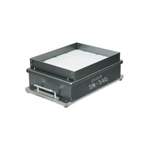
Camera-based component detection
Use controlled imaging to count small or complex components, verify a completed batch and identify selected wrong-part or presentation conditions.
Direct answer
A vision counting machine captures controlled images of components and applies validated rules to identify each accepted object. The count may be made while parts free-fall, travel on a belt, sit on a presentation surface or occupy a finished kit or tray.
Unlike a simple beam counter, vision can use shape, position, colour or multiple features. It should also return an explicit uncertain or reject result when the image does not support a dependable decision.
Vision architectures
Parts pass through a controlled imaging zone before a batch gate or pack discharge.
A spread layer travels through stable lighting, allowing more image time and reject control.
Vision identifies presented components and can guide selection where frequent changeover matters.
A completed layout is checked for required positions, quantities or selected wrong parts.
Quantity can be combined with proven checks for shape, colour, orientation or gross defects.
Vision, optical events and weight can be combined where independent evidence adds value.
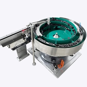
Where vision helps
Vision becomes attractive where a component has a complex silhouette, a single optical beam could merge touching objects, or the process needs recognition as well as quantity. It is not a substitute for handling: hidden parts, uncontrolled pile depth and unstable lighting can still create uncertainty.
Method comparison
| Method | Quantity evidence | Strong starting application | Main limitation |
|---|---|---|---|
| Optical beam | One sensor event per singulated part | Stable separated stream | Touching parts may appear as one event |
| Machine vision | Validated objects in an image | Shape, location or verification is useful | Occlusion and lighting must be controlled |
| Count by weight | Quantity inferred from net mass | Consistent homogeneous components | Piece-weight and tare variation affect confidence |
| Hybrid system | Two complementary measurements | Additional plausibility or reject screening | More interfaces and acceptance logic |
Validation plan
Frequently asked questions
Final suitability and performance depend on representative components, controlled imaging and agreed acceptance criteria.
Ask about your component →A controlled feed presents components within a defined field of view. Calibrated lighting and image rules identify accepted objects, convert detections into a batch quantity and coordinate the result with a gate, reject or pack-handling sequence.
A conventional optical counter normally records a beam interruption from each singulated part. Vision analyses an image, so it can use shape, position or multiple features, but it still needs controlled presentation, validated lighting and rules.
Sometimes, if the visible features remain sufficient for a validated rule. Complete occlusion cannot be solved by software alone, so feeding and product depth remain important.
Potentially. Presence, shape, colour, orientation or selected defect checks can be combined with quantity where resolution, lighting, cycle time and reject handling are proven for the approved component range.
No. Trials are needed to establish presentation, occlusion, lighting stability, false detections, changeover and the response to rejected or uncertain images.
Start with the component
We will identify whether vision, optical sensing, weighing or a hybrid route provides the most credible evidence.