Vibratory feed and optical count
A bowl or linear feeder separates parts into a controlled lane. A photoelectric, fibre-optic or laser sensor detects each part before the batch gate.
Strong fit: repeat components with a stable singulation route.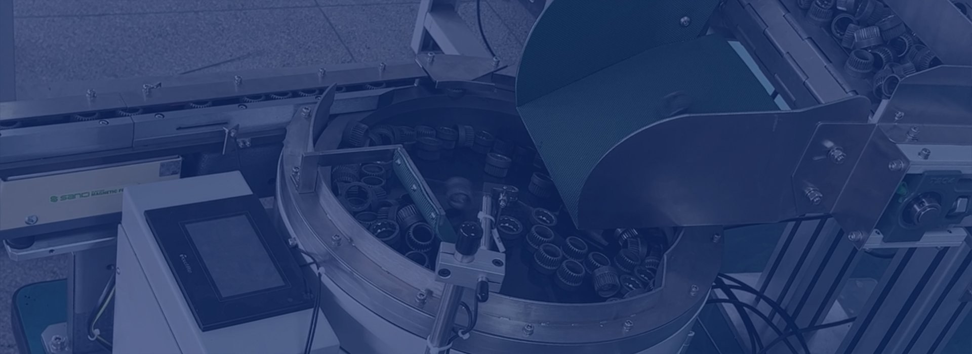
Counting system engineering
Compare feeding, singulation, sensing, gating and verification methods for accurate industrial parts counting and batching.
Quick answer
A sensor cannot correct two parts passing together or a component slipping through after the target has been reached. Counting performance is created by the combination of controlled bulk supply, singulation, detection, buffering, gate response and recovery logic.
The application review starts with the part and the required finished batch, then selects the most credible architecture.
System architectures
A bowl or linear feeder separates parts into a controlled lane. A photoelectric, fibre-optic or laser sensor detects each part before the batch gate.
Strong fit: repeat components with a stable singulation route.Components are lifted progressively from a low hopper and transferred to the counting point with less bulk recirculation.
Strong fit: longer, heavier, noisy or tangle-prone parts.Controlled imaging identifies individual items, overlaps or selected features where a single beam is insufficient.
Strong fit: complex silhouettes, verification or multiple objects in view.A sample-derived unit weight converts stable measured mass into a component quantity, with tare and tolerance controls.
Strong fit: consistent parts where singulation is unnecessary or impractical.Separate channels deliver different components into one bag, box or kit position, with recipe and completion logic.
Strong fit: repeat kits containing several defined part types.A buffer and escapement release one component or one preset quantity after a machine request.
Strong fit: assembly, insertion, test and operator-assist processes.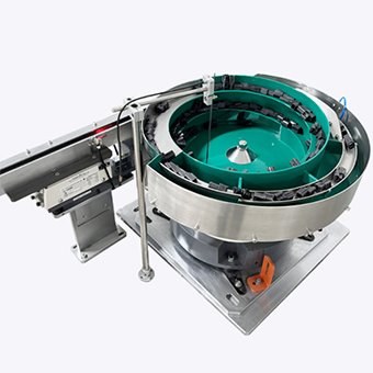
Sensor selection
Small, transparent, reflective, dark, irregular or fast-moving parts may need a specific sensor arrangement. The detection zone is assessed for beam size, contrast, response time, background, vibration and the risk of two parts occupying the sensing area together.
Design controls
Track tooling and pitch control prevent side-by-side or touching parts reaching the sensing zone.
Two-speed feeding, pre-count buffering or positive gating manage the final parts of the batch.
Low-level conditions, timeouts and operator recovery steps preserve a known count state.
Accumulation isolates the counter while a bag, box or kit position indexes into place.
Technology comparison
| Method | Primary strength | Key application checks | Typical destination |
|---|---|---|---|
| Vibratory + optical | Dedicated repeatable flow | Nesting, overlap, marking, sensor contrast | Bags, boxes, assembly |
| Step + optical | Gentle low-level feeding | Lift geometry, final orientation, buffer | Boxes, process feed |
| Vision counting | Complex detection and verification | Lighting, occlusion, image validation | Kits, trays, inspection |
| Count by weight | No one-by-one singulation | Unit-mass variation, tare, resolution | Bags, cartons, inventory |
| Multi-channel | Several components per recipe | Cycle balance, cross-contamination, reconciliation | Kits and service packs |
Frequently asked questions
Final suitability and performance remain subject to the actual component, operating conditions and agreed acceptance criteria.
Ask about your component →The best system is the simplest one that can reliably separate, detect and batch the full component range at the required sustained output. Geometry, material, speed, product variation and the receiving process determine the choice.
An optical sensor usually creates a count signal when a separated part interrupts or reflects a beam. Vision counting analyses images and can distinguish multiple objects or selected features, but needs controlled presentation, lighting and validated image rules.
Counting by weight can suit components with consistent individual mass and where exact singulation is difficult. Sample variation, scale resolution, tare management and tolerance determine whether it is suitable.
Yes, where the detectable difference and reject route are defined. A vision or dimensional verification stage may identify out-of-family parts before the completed batch is released.
Yes. Recipes, target quantities, completed batches, alarms and operator actions can be made available through the selected PLC, HMI or production-data interface.
Start with the component
We will identify the most credible feeding and counting route, then define the evidence needed for the next decision.